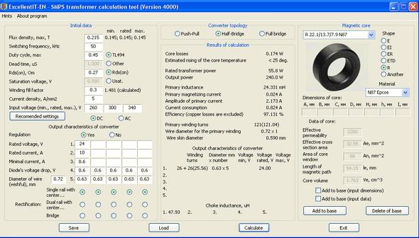
- #Excellent it smps transformer calculation tool full
- #Excellent it smps transformer calculation tool Pc
Once all the winding turns are determined, the wire size should be properly chosen to minimize the winding conduction loss and leakage inductance.
#Excellent it smps transformer calculation tool full
Note: Push-pull, forward, half-bridge, and full bridge converter topologies typically do not require an air gap, since it is actually true transformer action. The designer will verify that the gap is sufficient to prevent core saturation. The core gap will be determined by the number of primary turns and the inductance specification. In a specific application, optimum core utilization is associated with a specific optimum core gap length. The smallest size and lowest cost transformer is achieved by fully utilizing the core. P o = Output power Step 2: Volt-Time Product (V-µSec) Valueĭetermine the V-T value based upon the maximum allowable duty cycle and the frequency Step 3: Primary Turnsĭetermine the minimum number of primary turns required to support the worst case V-T value. K f = Form factor for square wave K f = 4 The W aA c / power output relationship is obtained by: The table below gives an overview of core types as a function of power throughput: Output power level (watts) A larger transformer must operate at a lower power density because the surface area dissipating heat does not increase in proportion to the volume producing the heat.
#Excellent it smps transformer calculation tool Pc

EE and EF are good choices and generally used with either vertical or horizontal bobbins (vertical bobbins are good when footprint space is at a premium).EFD and EPC cores are used when a low profile is required.The winding window area should be as wide as possible to maximize winding breadth and minimize the number of layers. The core shape and window configuration are important for high-frequency transformer design to minimize losses. However, temperature rise, and operating flux density will affect core losses, and this must be taken into account to ensure reliable operation. In general, this will not affect operation of the converter as long as the core is not close to saturation as the inductance (which controls the mode of operation) is primarily determined by the air gap. Permeability varies significantly with temperature rise and operating flux density.

For operation below 500 KHz, most designers will use a core material with a permeability of 2000 to 2500. Ferrite cores are the best choice for high-frequency applications. Make your preliminary core choice based upon the power requirements of the application, the switching topology, and the frequency. The following parameters are essential for designing SMPS magnetic components: Following these 12 steps can help engineers navigate the challenges and ensure a successful project. Designing magnetic components for SMPS can be challenging due to the increasing demands of modern electronics designs.


 0 kommentar(er)
